|

The Newman's Energy Machine
By JL Bayley York
created on 06-12-05 - usr inc -
last update on 08-29-06
|
All information and diagrams are published freely
(freeware) and are intended for a private use and not for a commercial
application
Disclaimer: The author assumes no liability for any incidental,
consequential or other liability from the use of this information. All risks and damages, incidental or otherwise, arising
from the use or misuse of the information contained herein are entirely the responsibility of the user. Although careful precaution
has been taken in the preparation of this material, I assume no responsibility for omissions or errors in the diagrams or
measurement datas published here. |
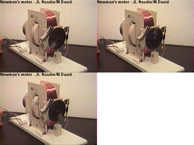
The Newman's Energy Machine V1.0 from JL Naudin, Blueprints
and pictures
ENERGY GENERATION SYSTEM HAVING HIGHER ENERGY OUTPUT THAN INPUT
No.Publication (Sec.) :WO8300963
Date de publication :1983-03-17
Inventeur
:NEWMANJOSEPH W (US)
Déposant :NEWMAN JOSEPH W
Numéro original: WO8300963
No. de depot:WO1981US0110519810828
No. de priorité :WO1981US01105 19810828
Classification
IPC :H02N11/00; H02K53/00
Classification EC :H02K53/00, H02N11/00B
Brevetscorrespondants :AU7583781,
BR8109038,
Abrégé A system for generating obvious work motion, or electromagnetic
energy (fields
offorce) or electric current utilizing the electromagnetic
energy which makes upa matter and results in a greater output
of energy, than
the initial input of conventional energy means and teachings. A first
exemplary embodiment (Figure1)
of the generator uses a contained fluid (117)
surrounding a series of aligned magnets (120); while a second exemplary
embodiment (Figure 3) uses a special material (201) held stationary between
two static magnets (202, 203),the special
material having its atoms aligned
but maintaining the resulting magnetic field at least substantially within
its boundary
surface; while third and fourth exemplary embodiments (Figures 5
and 6) utilize a relatively heavy coil (205) made up
of relatively large
diameter wire of relatively great length and number of loops and length and a
relatively small
energizing current to drive a rotatable permanent magnet
(200).

Click on the picture to see the FULL PATENT
|
 Email : usr.york@lycos.com Email : usr.york@lycos.com
|

